Carter DiOrio
MSR Student @ NorthwesternAnalysis of Fiducial Markers and Camera Calibration
Fiducial Analysis
Github repository: https://github.com/CarterDiOrio/FiducialMarkers
The original aim of of the project was to find the best method to detect an April tag using a Intel Realsense D435i camera. To evaluate whether one approach was better or not we needed a method to evaluate the accuracy and precision of the fiducial and detection method combo.
Experimental Setup
To provide a ground truth transform between the camera and the tag for accuracy evaluation I used a Vicon optical tracking system. Since our system has a small workspace it can measure position with an accuracy on the order of tens of microns.
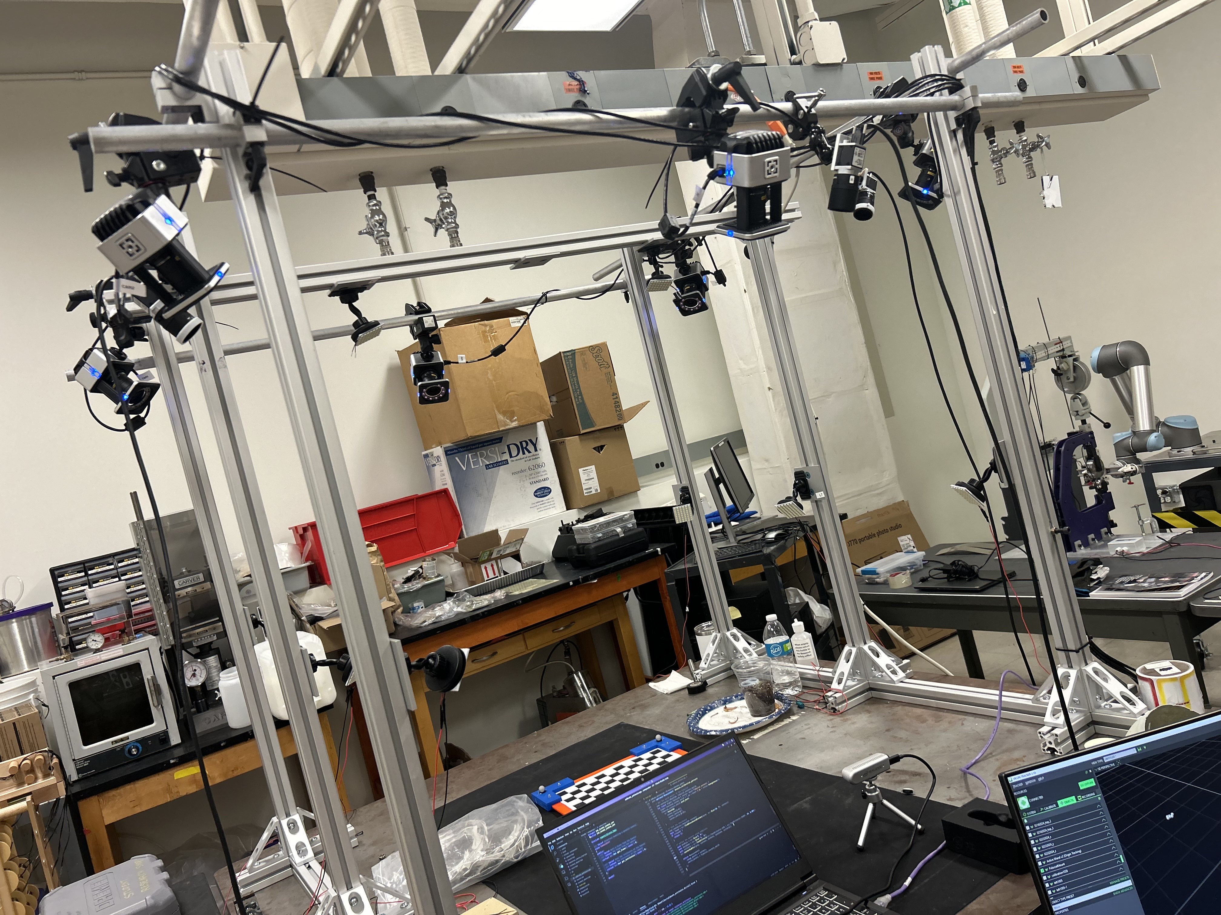
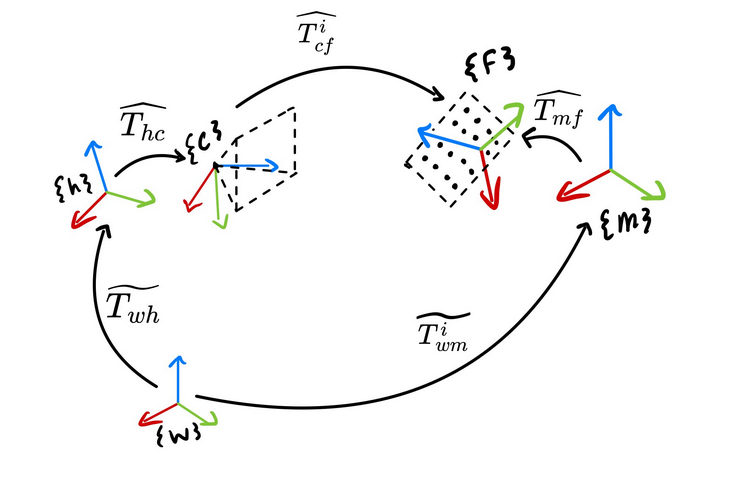
Tracking markers were then mounted to both the camera and the fiducial. This setup still does not directly give the ground truth transform. It gives us the transform between the markers attached to the camera (the hand) and the markers attached to the fiducial (the mount). To get a measurement of T_camera_fiducial from the Vicon we need to calibrate two more transforms: the camera relative to the hand (T_hand_eye) and the fiducial relative to the mount (T_mount_fiducial). Knowing these two transforms completes the loop and establishes a ground truth estimate as shown below with the vicon as the world frame.
One major issue with this is that if we perform the calibration with a chessboard in the mount, then disassemble the mount to put the tag we want to evaluate in it, the calibration is now invalid. Instead of paper tags that have to be swapped, an non-emissive paper like e-ink display can be used to display the tags. Using a lower level library to access the display we can exactly control how each fiducial is rendered, this ensures the T_mount_fiducial transform is transferable since we can render each calibration pattern or fiducial such that their origins are all in the same location. An added benefit is it also removes the additional position error that results from trying to repeat the same trajectory with each tag since for each position all the tags can be displayed on the display automatically.
At its core the optimal calibration must minimize the reprojection error of all features as shown in the equation below, where every fiducial feature X has a corresponding image feature y, and p() is the projection function. Using a dense (26x26) chessboard as the calibration pattern I performed nonlinear optimization and the result was a 0.33 mean pixel reprojection error and a 0.25 millimeter mean translational error of the extrinsics.

Precision Results
For each of the three fiducials under test, Chessboards, April tags, and ArUco markers, I assessed their accuracy over increasing distance and varied orientations.
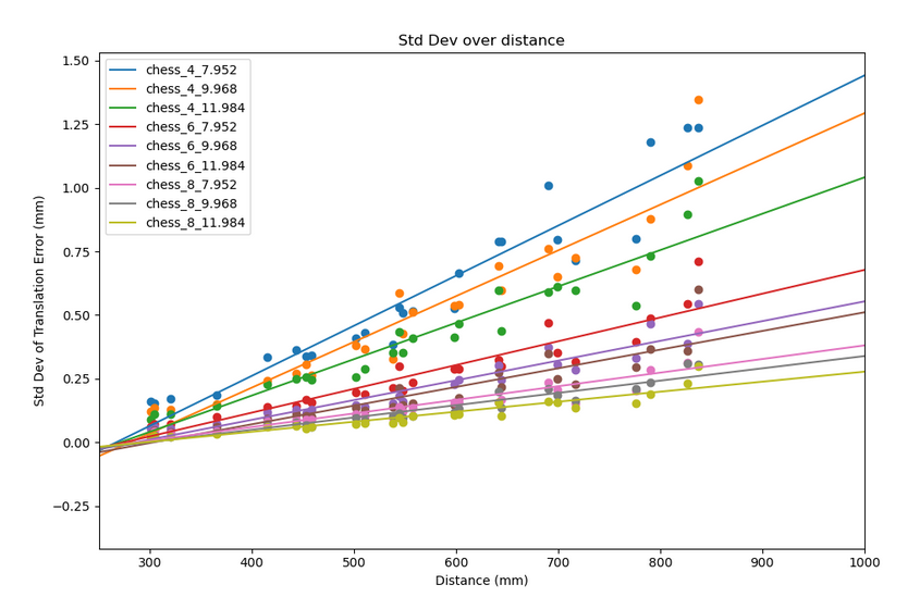
Starting off with the chessboard above. Each chessboard is denoted by its number of squares and then the size of each square in millimeters. The sizes happen to be these non-whole numbers because they need to align with the nearest whole number of pixels on the eink display. For my experiment setup the dominant factor in the accuracy of the chessboard is the number of squares. Each "band" of square sizes are perfectly seperated from each other in this plot and within each band the precision increases with square size. This confirms the common knowledge of more and larger corners is better, and that the number of corners should be increased till diminishing or negative returns.
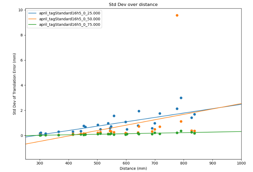
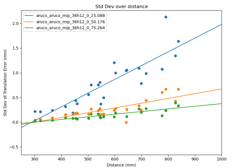
Above on the left and right we have the April tag and ArUco results respectively. The April tag results have a significant outlier and I left it in to show that, at least in my usage, sometimes the April tag library produces significant outliers and that needs to be taken into account. However in their best case with both tags at 75 millimeters the April tags have better precision with 0.04, 0.04, 0.14 millimeters of standard deviation on the XYZ axes compared to 0.05, 0.05, and 0.17 millimeters of standard deviation on the ArUco markers. These results are close enough that it could be argued it is within margin of error, but the best advice I could give is to benchmark it for your specific scenario. For example, I noticed the April tag detector works better on with the e-ink display (it has slight glare) than the ArUco detector does.
Conclusion
Planar fiducials like chessboards, April tags, and ArUco markers, can be very precise depending on your needs. With larger tags and a limited workspace you can expect sub-millimeter std deviations on all three axes with deviations getting as low as ~0.05mm, ~0.05mm, ~0.17mm on the XYZ axes respectively. Even if your workspace falls outside this definition, it has been shown that the precision scales linearly over distance within reasonable workspace and tag orientation envelope. However you can expect a large dropoff in precision and detection suddenly at further distances according to the April Tag 2 and ArUco papers. Some of this dropoff is attributed to effects like feature detection noise increasing non linearly with the distance to the feature.
It is of note that accuracy is extremely difficult to test empirically and it is why there is no "Accuracy Results" section. Most major fiducial papers, even those claiming high accuracy like Rune Tags, use synthetically generated images for their experimental accuracy validation. These are careful simulations, but a method does not exist to empirically evaluate it on your specific camera setup. This is because you need the ground truth transform between the camera's center of projection and the tag. The tag's world position can either be surveyed or measured in a variety of ways, but the camera's center cannot be directly measured. It needs to be estimated using information from the camera itself, and as far as I could find an extrinsic calibration method does not exist that gives sufficient accuracy and precision guarantees to meaningfully measure the accuracy of the tags. Empirically measuring the accuracy of tags is getting further into the area of serious metrology and statistics than the realm of typical computer vision and any further work needs to treat it as such.
I also did not cover the rotational precision because planar fiducial markers also need to deal with a orientation ambiguity that exists in planar PnP (See [2]). This effects all standard planner patterns including chessboards but to a lesser extent. Solutions to this vary as covered by [2], but include modifications to the tag, averaging, filtering, and tracking. However, ignoring this effect, it scales linearly like the translational error within a reasonable workspace.
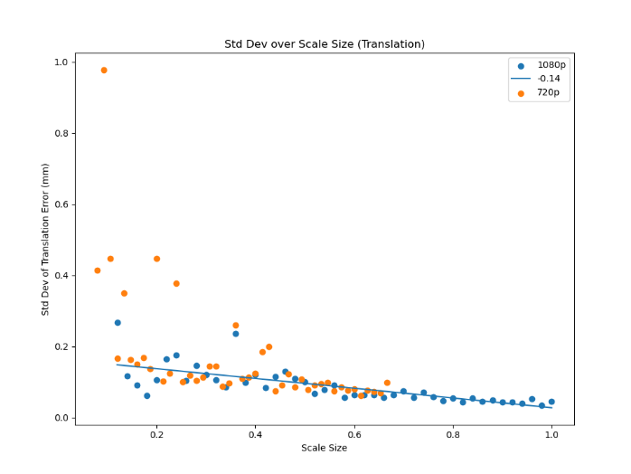
I did not have the time or setup required to explore this fully, but for future work, if you could prove that the relationship is extrapolatable back to the normal case it might be possible to use a camera that has significantly higher resolution to perform the extrinsic calibration then set it to a significantly lower resolution and move the tag far enough away that the tags error becomes the dominating factor. The one issue with this is that tags are quite robust to lower resolutions. As shown in the chart below, I measured the std deviation of a stationary 75mm April tag at half a meter while continually decreasing the resolution by scailing the image down with the X axis being the percentage of 1080p. The reason I resorted to scailing is because most cameras (like the Realsense I was using) only have a few fixed resolutions they can operate at and it is not enough to get a good line fit. To make sure I was not exaggerating the tags effectiveness by introducing interpolated information due to downscailing from a higher resolution I repeated the test but started at 720p and that is shown in orange and it matches the 1080p results. This is a great result for the tags, but it means this thrust of future research would require a camera that could go up to a significantly higher resolution.
MrCal
Github repository: https://github.com/CarterDiOrio/mrcal_ros
Although it's challenging to empirically measure, one of the most critical factors affecting the accuracy of your tag's position measurements is your camera's intrinsic parameters. There's no substitute for using a robust framework and dedicating the effort to achieve precise calibration. One of the best open source frameworks that attempts to give statistical feedback and guarantees is MrCal [3] developed by NASA's JPL. MrCal's documents and tutorial explains all of its analyses in detail, but I will give a short example about how it can approve even a well behaved lens as motivation. The plots in this section are from MrCal, which also serves as the source of all background information. For this example, I used approximately 400 images of a dense chessboard (26x26) as the calibration data
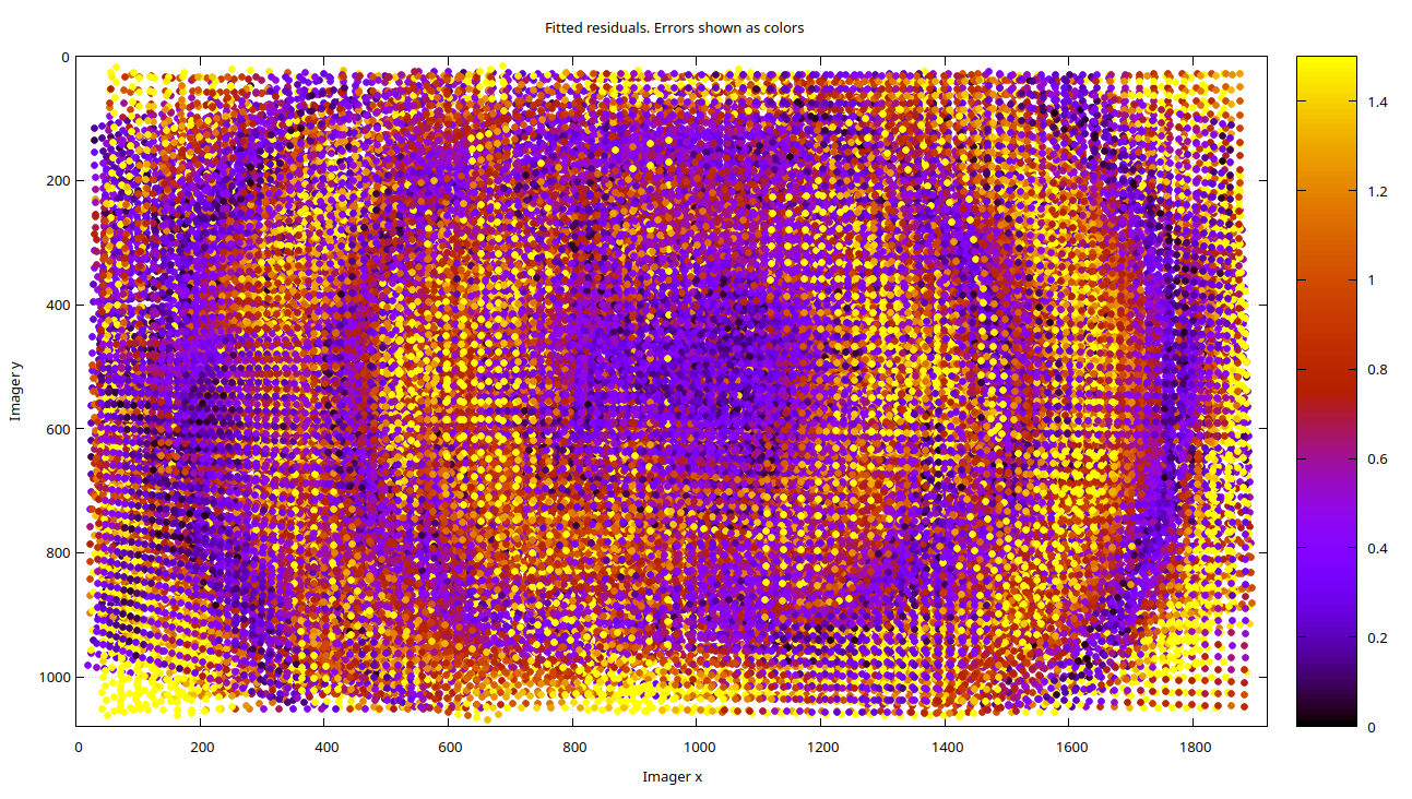
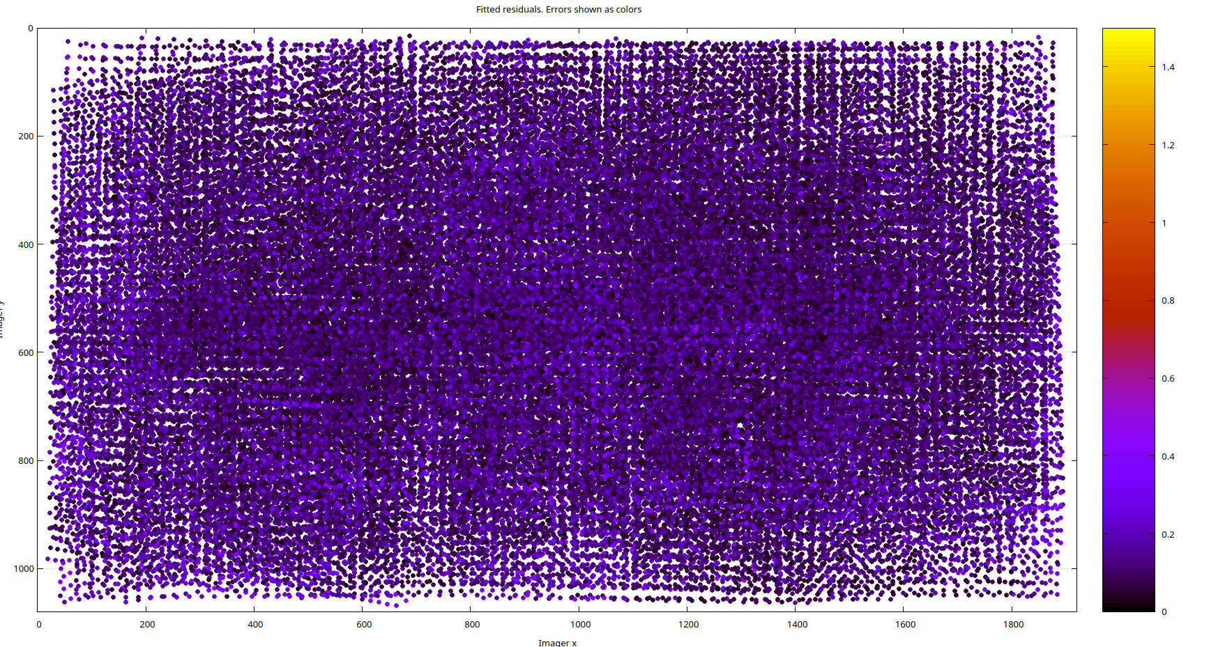
The Intel RealSense D435i's color lens does not come with distortion coefficients (see https://github.com/IntelRealSense/librealsense/issues/8325 and https://github.com/IntelRealSense/librealsense/issues/1430). Intel's opinion is that it reduces about 1px of reprojection error at the extremess, and at first glance, the lens appears to be well-behaved. However, when we use a pinhole model and examine the reprojection error residuals from calibration, we observe clustering in the residual magnitudes, as shown below. Clustering of this kind indicates lens distortion, assuming other factors like rolling shutter have been accounted for. Since our chessboard corner detection error is roughly normally distributed, a fully modeled lens should also yield normally distributed residual errors in both magnitude and direction, which should appear as noise
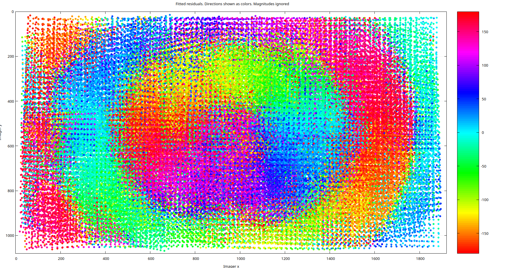
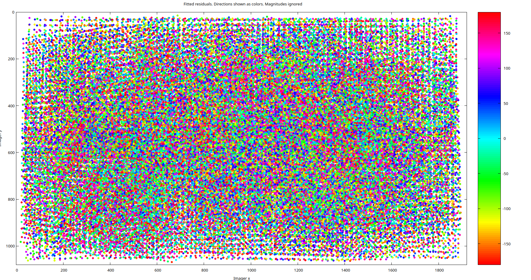
As for the residual directions, shown below for the pinhole model, they also exhibit a high degree of clustering. It's important to emphasize that this isn't due to a poor calibration but rather to modeling error. No amount of refining the pinhole parameters will resolve this issue because the D435i's color lens simply isn't a pinhole lens. Even if you don't require the enhanced accuracy provided by a more complex model, MrCal offers tools to help you make an informed decision.
Moving onto a richer model, if we rerun the calibration with MrCal's Splined-Stereographic lens model those two plots turn into noise below like we would expect in the ideal case, and this is a result of modeling the lens correctly.
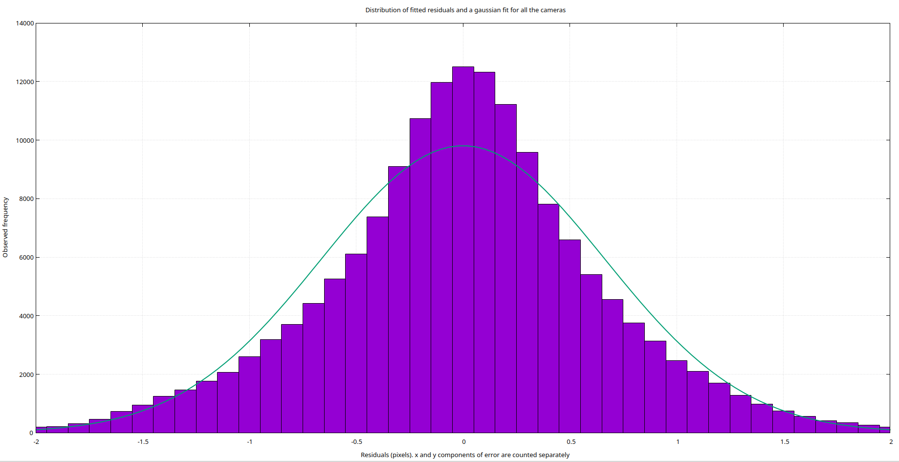
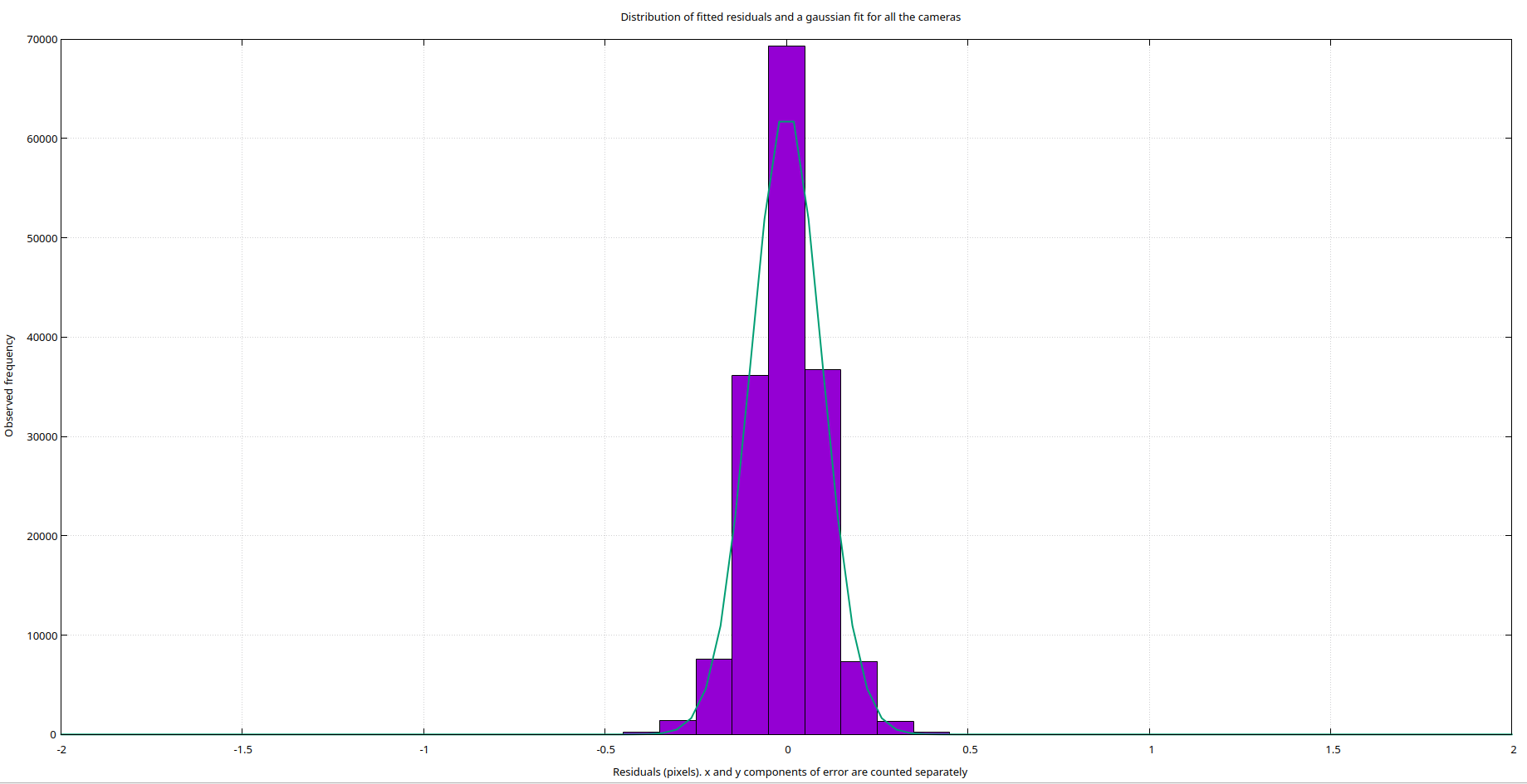
A benefit of correcting the modeling errors is our reprojection error decreases subsantially. The two histogram's below show the distribution of the residual error. On top is the pinhole model with an RMS reprojection error of 0.7 pixels, and on the bottom is the spline model with an RMS reprojectin error of less than 0.1 pixels. A concrete example of the spline model significantly helping was in the extrinsic calibration of the fiducial analysis setup. Using the MrCal model compared to the built in realsense intrinsics brought the translational error of the extrinsics down to 0.25 millimeters from 0.75 millimeters with no additional changes.
Targetless Hand Eye Calibration
Github repository: https://github.com/CarterDiOrio/SfMHandEye
As part of a new research thrust for exploring using a highly accurate robot arm, the Mechademic 500, to improve on and make transferable hand eye calibrations, I implemented a targetless hand eye calibration routine. It works by using Structure From Motion to reconstruct the environment from random camera poses with the robot's motion providing the scale of the scene. Once the environment and camera positions are reconstructed, the environment itself takes the place of the calibration target to give the trajectory of the camera in the camera frame. The hand eye calibration is then found using Bundle Adjustment. The above video is the 3D point cloud from the SfM reconstruction of the MSR lab environment with the green dots being the registered camera poses. The below video showcases the hand eye calibration by commanding the robot to pivot about the color camera sensor of the camera.
To evaluate the hand eye calibration accuracy I used a similar test to [5]. I had the robot move to poses that observed a ChArUco board. The ChArUco board provided the movement in the camera frame and then the average translation errors where found by comparing the expected and actual camera motion using the Hand Eye transform. It achieved a mean translational error of 1.7 millimeters and a mean rotational error of 0.37 degrees. To compare this against an industry solution, Zivid an industrial 3D camera manufacturer, provides a target based hand eye calibration solution and this targetless solution exceeds it in rotational accuracy while falling slightly behind in translation accuracy (See Zivid Results here: https://blog.zivid.com/importance-of-3d-hand-eye-calibration)
Citations
- Enebuse I, Ibrahim BKSMK, Foo M, Matharu RS, Ahmed H. Accuracy evaluation of hand-eye calibration techniques for vision-guided robots. PLoS One. 2022;17(10):e0273261. Published 2022 Oct 19. doi:10.1371/journal.pone.027326
- H. Tanaka, Y. Sumi and Y. Matsumoto, "A solution to pose ambiguity of visual markers using Moiré patterns," 2014 IEEE/RSJ International Conference on Intelligent Robots and Systems, Chicago, IL, USA, 2014, pp. 3129-3134, doi: 10.1109/IROS.2014.6942995.
- https://mrcal.secretsauce.net/
- M. Krogius, A. Haggenmiller and E. Olson, "Flexible Layouts for Fiducial Tags," 2019 IEEE/RSJ International Conference on Intelligent Robots and Systems (IROS), Macau, China, 2019, pp. 1898-1903, doi: 10.1109/IROS40897.2019.8967787.
- H. Xie, C. -t. Pang, W. -l. Li, Y. -h. Li and Z. -p. Yin, "Hand-eye calibration and its accuracy analysis in robotic grinding," 2015 IEEE International Conference on Automation Science and Engineering (CASE), Gothenburg, Sweden, 2015, pp. 862-867, doi: 10.1109/CoASE.2015.7294189.